What a Solar Channel Roll Forming Machine Produces
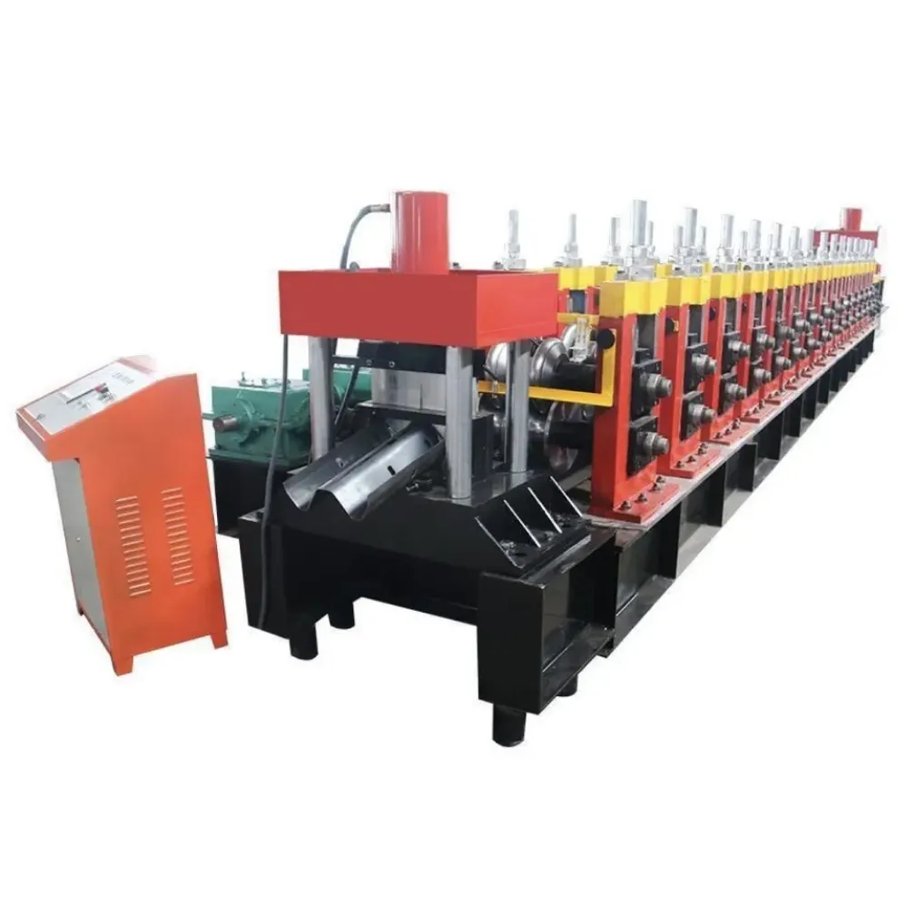
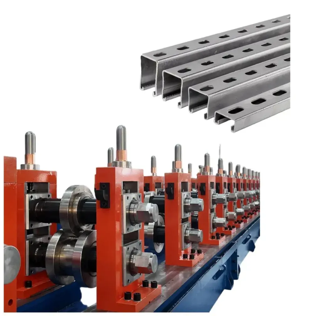
Solar mounting structures are built from roll-formed steel channels: the rails that hold the modules, the posts that carry the array, and the bracing that stiffens it against wind. A solar channel roll forming machine produces these members from coiled strip in one continuous operation, with clamp slots and fixing holes punched inline and each piece cut to the project length. The same equipment is also referenced as a solar strut channel machine or a PV bracket production line; the product scope on this page covers the 41-series channel range and the C and U sections commonly specified in solar mounting designs.
Anatomy of a Solar Mounting Structure
A ground-mounted array typically combines three roll-formed parts. Mounting rails run under the modules and take the clamp loads. Posts or piles support the rails and transfer load to the foundation. Bracing members connect posts and rails into a rigid frame. Rooftop systems use lighter rail sections with the same clamp interface. Each part has its own section geometry and hole pattern, and all of them are cold-formed products. A producer serving the solar market therefore needs one line that covers the full section family, with size changes handled from the control panel rather than by rebuilding tooling.
Why ZAM and Galvanized Strip Dominate Solar Sections
Solar mounting members sit outdoors for the full service life of the array, which is designed around twenty-five years of module operation. Plain black steel fails this requirement, so the market runs on coated strip. Pre-galvanized and hot-dip galvanized strip are the established options. ZAM strip, a zinc-aluminum-magnesium coating, has gained share because the coating resists cut-edge corrosion far better than conventional galvanizing, which matters on roll-formed parts where every cut end and punched hole exposes bare steel. This line is specified for coated strip throughout: roller and die surfaces are prepared to run zinc and ZAM coatings without scoring or flaking.
Punching Patterns for Clamp Interfaces
Solar channels carry more punching than most structural profiles. Rails need slot rows where module clamps bolt on, posts need fixing holes at calculated positions, and bracing members need connection holes at both ends. Slot geometry also differs between module brands and clamp systems, so a producer rarely runs one pattern for long. Servo-fed hydraulic punching stations on this line take the pattern from the order drawing through the touch screen, and die cassettes exchange when the clamp standard changes. The punched strip enters the mill with every hole already in final position, which removes the drilling line that older solar fabrication shops still operate.
Built for High-Volume Solar Orders
Solar mounting contracts run to container-load quantities with tight delivery windows. The line configuration reflects this: a butt welder and horizontal looper keep the mill running through coil changes, the tracking cut-off shears without stopping the strip, and automatic stacking accumulates finished members for strapping and dispatch. One operator can supervise the full line, which keeps labor cost per ton competitive on large array projects.
What To Prepare Before Requesting a Quote
- Section drawings for the rail, post and bracing profiles of the mounting system
- Clamp slot and hole pattern drawings, with the module or clamp brand if fixed
- Strip specification: coating type, thickness range and material grade
- Monthly output target and the main cut lengths in the order book
- Site power supply and any required electrical component brands
FAQ
How does a solar channel machine relate to a strut channel machine?
Solar mounting rails and posts in the 41-series range are strut-type channels, so the two machines overlap. A line specified for solar production adds the clamp slot patterns, coated-strip tooling and high-volume configuration that solar orders demand. The product drawings decide the final tooling layout.
Which sections can one line produce?
The standard tooling covers the 41-series channel family. C and U sections for posts and bracing are added per drawing at order stage, and size changes within the covered range are made from the control panel.
Can the line form ZAM strip without damaging the coating?
Yes. The rollers and punching dies are specified for coated strip, with surface preparation matched to zinc and ZAM coatings. Coating integrity is checked during the pre-delivery trial run on the actual order material.
What output speed should a solar producer expect?
The rated range is 15-40 m/min. Hole-dense rail sections and short bracing pieces run toward the lower end, while plain sections at standard lengths reach the upper end.
What delivery and installation terms apply?
Standard configurations ship in 30-45 days and customized lines in 60-90 days, after a factory trial run. THRONCH engineers install and commission the line at the buyer site and train the operating team during commissioning.