What a U Purlin Roll Forming Machine Produces
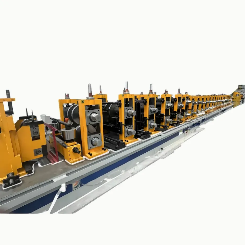
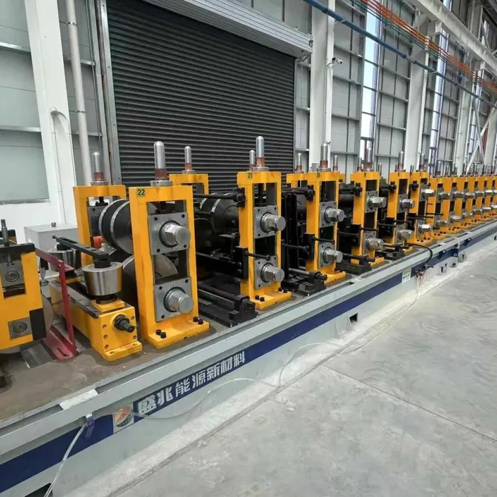
A U purlin, also called a plain U channel, is a cold-formed steel section with two parallel flanges and no edge lips. The open, symmetrical shape makes it easy to cut, drill, weld and connect, which is why the U41-U82 size family became the standard profile range for solar PV mounting rails, seismic bracing and utility tunnel support frames. The machine on this page forms these channels continuously from 1.5-3.0 mm strip: leveling, inline punching, roll forming and hydraulic cut-off happen in one pass, and finished channels are stacked automatically at the line end.
Where U Channels Are Used
- Solar PV mounting structures: rails, posts and bracing members for ground-mounted and rooftop arrays
- Seismic bracing systems: lateral and longitudinal braces for pipe, duct and cable support in buildings
- Utility tunnel and pipe gallery frames: support channels for integrated municipal corridors
- Light steel framing: purlins, base rails and connection members where a plain channel section is specified
Line Configuration
The brochure configuration for the U profile line includes the following stations:
- Coil loading car and uncoiler
- Leveling unit
- Shearing and butt welding unit with horizontal looper
- Servo-fed multi-station hydraulic punching
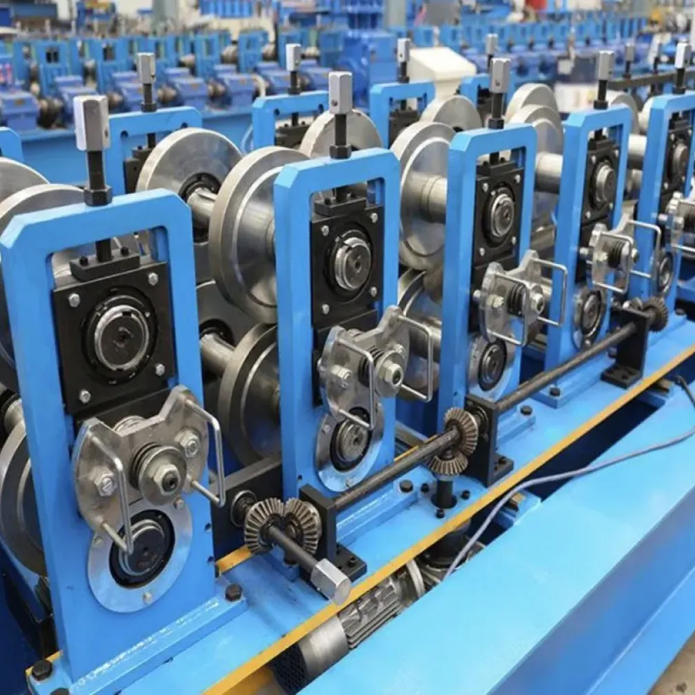
- Roll forming mill with archway structure
- Hydraulic cut-off, conveyor roller table, automatic stacking and discharge
The butt welder and looper keep the mill running through coil changes. For channel producers serving solar projects, where daily output decides contract profitability, this combination removes the main source of unplanned stops on the line.
Punching: The Core Station of a U Channel Line
U channels for mounting and bracing systems carry far more holes than structural purlins: fixing holes along the web, connection holes at set intervals, and often slots for adjustable fittings. Producing these holes offline means a second handling step and position errors between batches. On this line, servo-fed hydraulic punching stations work ahead of the mill, with hole diameter, pitch and position taken from the order drawing through the touch screen. The punched strip then forms with the holes already in final position, and the hydraulic cut-off finishes each channel to length. Die sets are built per hole pattern and can be exchanged when a new project standard arrives.
U, C and Z Sections: Which Machine Covers What
The three purlin-family sections differ in flange design. A U channel has plain flanges without lips. A C purlin adds stiffening lips to the flange edges for higher bending capacity. A Z purlin offsets the flanges so sections can lap into continuous spans. A dedicated U line, as described on this page, suits plants whose volume sits in the 41-series channel range for solar and seismic markets. A C purlin line can also form plain U sections within its tooling range, which suits mixed producers. Buyers supplying several section types should state the full product mix at inquiry, so the mill and cut-off tooling are laid out for the real workload rather than a single profile.
What To Prepare Before Requesting a Quote
- Channel drawing with width, height, thickness and any lip or return details
- Hole and slot pattern drawings for the intended mounting or bracing system
- Material grade and surface, for example hot-rolled, cold-rolled or pre-galvanized strip
- Daily or monthly output target for the main channel sizes
- Site voltage and frequency, with any required electrical component brands
FAQ
What is the difference between a U purlin and a C purlin?
A U purlin has plain flanges without edge lips, so it is lighter and easier to connect but carries less bending load. A C purlin adds lips to the flange edges, which stiffens the section for structural purlin duty. U channels dominate in mounting and bracing systems; C sections dominate in building frames.
What does the U41-U82 size range mean?
It is the standard channel size family used in solar mounting and seismic bracing systems, covering sections from 41×41 mm up to 41×81 mm. One tooling set on this line covers the full family, with size changes set from the control panel.
Can this line produce slotted channels?
Yes. Slots are punched inline by the servo-fed hydraulic stations before forming. Slot length, width and pitch follow the drawing entered on the touch screen, and die sets are exchanged when the pattern changes.
How fast does the line produce?
The rated range is 15-40 m/min. Actual speed depends on the punching workload per meter and the cut length, since hole-dense patterns and short pieces keep the line at the lower end of the range.
What delivery and after-sales terms apply?
Standard configurations deliver in 30-45 days and customized lines in 60-90 days, each after a trial run with the order material. THRONCH engineers install and commission the line at the buyer site and remain available for technical support and spare parts after handover.