

Strut channel is the standardized cold-formed steel framing system used to support pipes, conduits, cable trays, HVAC equipment, and solar panels in buildings and industrial plants. The section is a U-shaped channel, most commonly 41 mm wide, with inward-curved lips along the open side. Spring nuts lock into those lips at any point along the length, so a support structure can be assembled, adjusted, and extended with hand tools and no welding or drilling on site. That adjustability is the reason strut channel became the default support system in mechanical, electrical, and plumbing (MEP) work worldwide, and why demand tracks data center, solar, and infrastructure construction. This guide covers the standard types and sizes, material and finish choices, seismic bracing requirements, and how strut channel is produced on a roll forming line.
What Is a Strut Channel?
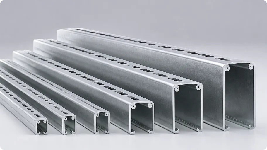
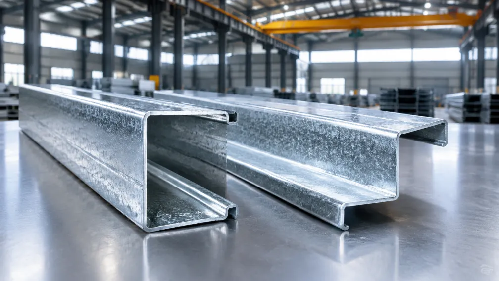
A strut channel is a continuous cold-formed section with three working features: a U-shaped body that carries the load, lips on the open side that grip the spring nut, and a pattern of holes or slots punched along the back for direct fastening. The system works because every component is standardized. Channels, spring nuts, fittings, clamps, and brackets from the same size family fit together regardless of when or where they were made, which lets installers treat the channel as an erector set for supports.
The load path is simple: the pipe or cable load hangs from a clamp or trapeze bolted through spring nuts into the channel, the channel spans between hangers or posts, and the hangers transfer the load to the building structure. What is less obvious is that the section also works in compression, so the same profile serves as columns and braces in support frames, which is what makes it the standard material for seismic bracing.
Strut Channel Types and Standard Sizes
Two dimensions define a strut channel: width and height. The international standard width is 41 mm (1-5/8 inch in the Unistrut sizing convention). Height and wall thickness set the load capacity:
| Profile | Dimensions | Thickness | Typical use |
|---|---|---|---|
| 41 x 21 mm | Shallow single channel | 1.5-2.0 mm | Light conduit and cable supports |
| 41 x 41 mm | Standard single channel | 1.5-2.5 mm | General pipe, duct, and tray supports |
| 41 x 41 back-to-back | Two channels welded or bolted | 1.5-2.5 mm | Columns, heavy trapezes, long spans |
| 41 x 62 mm | Deep single channel | 2.0-2.5 mm | Long-span trapezes, heavy pipe racks |
| 41 x 82 mm back-to-back | Deep double section | 2.0-2.5 mm | Seismic braces, structural frames |
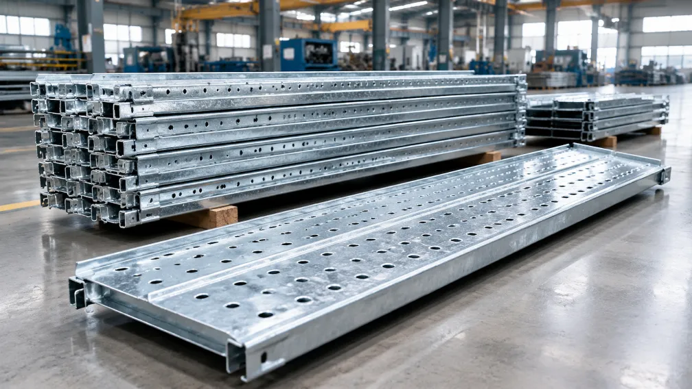
Three slot patterns cover the market: solid channel for maximum strength where fittings bolt through drilled or factory-punched holes, slotted channel with continuous long holes for adjustable fastening, and half-slot or punched-hole versions that balance strength with installation flexibility. Lengths are standardized at 3 m and 6 m in metric markets and 10 ft and 20 ft in North America.
A related profile family is the solar mounting channel, which shares the same lip-and-nut principle in shapes optimized for photovoltaic racking; producers serving both markets often run strut profiles and solar channels on related tooling, as covered on our solar channel roll forming machine page.
Materials and Finishes
Base material is structural carbon steel strip in yield strengths from 235 to 355 MPa. The finish is chosen for the corrosion environment, and it determines both service life and price:
- Pre-galvanized (mill galvanized) strip, typically Z275, is the standard indoor choice and the lowest-cost option, because the coil arrives already coated and needs no treatment after forming.
- Hot-dip galvanized after fabrication, to ISO 1461 or ASTM A123, suits outdoor and corrosive industrial sites; the formed and punched channel is batch-dipped, so the zinc covers cut edges and hole walls.
- Zinc-aluminum-magnesium coated strip offers two to three times the corrosion life of conventional zinc at similar coating weight, and is increasingly specified for solar and coastal projects.
- Stainless steel (304 or 316) serves food plants, chemical facilities, and marine environments.
- Powder-coated finishes over galvanized steel add color coding and extra barrier protection for architectural or corrosive interiors.
Seismic Bracing and Support Applications
The fastest-growing specification area for strut channel is seismic bracing of building services. Codes such as ASCE 7 in the United States, EN 1998 (Eurocode 8) in Europe, and GB 50981 in China require suspended pipes, ducts, and cable trays above defined weight or size thresholds to be restrained against earthquake motion. A seismic brace assembly is straightforward: a strut channel member runs at an angle, normally 45 degrees, from the supported pipe or trapeze back to the building structure, using rated end fittings. The channel works in tension and compression, so one profile handles both directions of sway.
Designers size the brace from the seismic design force, the brace angle, and the connection capacity, and the published load tables for the channel section govern the allowable axial load over the unbraced length. This is one application where dimensional consistency of the channel matters directly for safety: a spring nut that slips or a lip that yields under a seismic load defeats the whole restraint. Utility tunnel and underground pipe gallery projects, such as the Susong earthquake-resistant pipe gallery supports project, show how these bracing systems are engineered and installed at infrastructure scale.
How to Specify Strut Channel for a Project
Four inputs settle a strut channel specification. The first is the load: the weight of the supported services per meter, plus any dynamic allowance, decides whether a 41 x 21 mm channel suffices or a 41 x 41 or deeper section is required, and the manufacturer's published load tables give the allowable uniform and point loads at each span. The second is the support spacing, because allowable load falls quickly as the span grows; moving hangers from 3 m to 1.5 m roughly doubles what a given channel carries. The third is the environment, which fixes the finish as described above. The fourth is the connection: spring nut type and bolt grade must match the channel lips, and for seismic work the entire assembly, channel, fittings, and anchors, must come from rated, tested components. Specifying all four at purchase avoids the common site problem of mixed components that fit loosely and derate the assembly.
How Strut Channel Is Manufactured
Strut channel is a pure cold roll forming product: galvanized strip is decoiled, leveled, punched with the slot or hole pattern, and progressively bent through roll stands into the lipped U profile, then cut to length by a flying shear. The process fundamentals are the same as those described in our article on what a cold roll forming machine is, but two features define a strut line specifically.
The first is the punching unit. The slot pattern must hold tight positional tolerance over the full length, because fittings and nuts locate from those slots, so lines use a high-speed press synchronized to the strip feed, with quick-change cassettes when switching between solid, slotted, and punched patterns. The second is the forming of the inward lips. The lips are bent past 90 degrees against the natural springback of high-strength strip, which calls for more forming passes than a simple channel and careful roll design around the final stands.
A dedicated strut channel roll forming machine runs the full 41 mm family, 21 to 82 mm in height and 1.5 to 2.5 mm in thickness, with size changeover by spacer and roll adjustment rather than roll replacement. Line speeds of 15 to 25 m/min are standard, and an automatic roll forming machine configuration adds auto stacking, bundling, and length-batch control so one operator can run the line.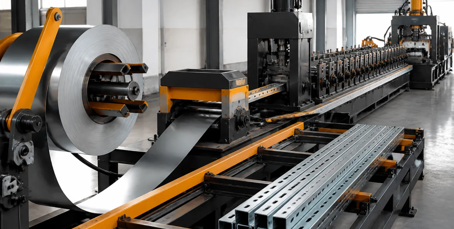
Get a Strut Channel Line Proposal for Your Profile Range
Send us your profile drawings or the channel sizes, slot patterns, and thickness range you plan to produce, together with your target output, and THRONCH engineers will return a line configuration with punching unit, roll pass design, and automation level matched to your market. Standard lines are completed in 35 to 50 days, and every line passes a 48-hour trial run with real strip before packing. Contact us at amy@thronch.com.
-

THRONCH
Cold Roll Forming Machine Manufacturer
THRONCH is a direct manufacturer specializing in custom cold roll forming lines and welded pipe mills. With over a decade of engineering expertise, we share technical insights and deliver high-precision